- Published 18 Apr 2023
- Last Modified 29 Aug 2023
- 6 min
Guide to Electric Actuators
What are electric actuators? Find out everything you need to know about different types of electric actuators, including their advantages and disadvantages.

Reviewed by David Carmichael, Solution Engineer (January 2023)
Every day, we all use actuators of various kinds without ever realising. The fact that their work goes on beyond our consciousness just proves how reliable, intuitive, and essential they are to modern living. In this article, we’ll be looking at what they are, how they work and the various types that are available.
What is an Electric Actuator?
The word “actuate” simply means putting a machine into action. However, the word “actuator” refers to a specific family of machines that move or control something, with the emphasis being on movement. They convert energy, be it electric, pneumatic or another form, into linear or rotary motion. As the name suggests, electric actuators directly require a voltage to operate.
Linear actuators have a limited travel distance because they are in the form of a shaft that moves backwards and forwards along its length. That doesn’t necessarily mean they are short – they can move over several metres. However, because of the way they operate (see below), it’s often more efficient to use another form of machine to move things quickly over long distances, unless there’s a particular need for precision.
Linear actuators don’t necessarily move simply between point A and point B – they can stop at any point along the way. If you imagine an electric car window or a dentist’s chair with adjustable height and angles, there needs to be a way to have the object positioned exactly as desired, not at one of two extreme positions. But also consider something like a movable solar panel, where its optimal orientation moves gradually as the day goes by – gentle, continual, and precise motion is exactly what an electric actuator can deliver.
Rotary actuators have no such limits as they are on a continuous loop, although they do tend to be used to move objects around sub-360-degree angles because the angle of rotation can be accurately controlled – that makes them perfect for operating valves or gates, for example.
Types of Electric Actuators
There are just two types of electric actuators – linear and rotary. Of course, they all come in a range of sizes, powers, and degrees of precision, and deciding on the right model of actuator is the job of the engineer or designer.
How Does an Electric Actuator Work?
An electric actuator is a form of mechanical power transmission based on a motor. Electric linear and rotary actuators work in different ways.
How Does an Electric Linear Actuator Work?
An electric linear actuator must convert the rotary motion of the motor into linear motion. There are multiple ways of doing that, as demonstrated by trains, conveyor belts and even clay pigeon launchers, but there’s a specific need in the electric actuator that the shaft will stay in its place when it’s put there – that is, it will lock in place even if the power is cut off. A car’s electric parking brake must not suddenly release if the battery runs out, for example.
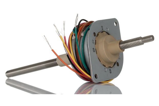
The best solution for this is to have a threaded rod and a threaded component of the actuator shaft, rather like a nut and bolt. If the nut is prevented from rotating when the bolt is rotated, by attaching it to some sort of guide rail, then when the bolt rotates, the nut will move forwards or backward, depending on the direction of rotation. If the threaded rod is connected via the nut and bolt to a shaft running parallel with it, you have your linear motion, and it won’t be able to be forced backwards or forwards once the power is off.
The simple nut and bolt model isn’t the only way to move the shaft along the threaded rod – they sometimes use ball screws or roller screws, which can be more expensive and have more parts but will often lead to greater speed, durability, and quietness thanks to the reduced friction.
Electric linear actuators have stop switches at either end, which will cut the power for that direction once it reaches either extreme. They might also have electronic sensors built in that can send information to the controller about its current position, which means that power can be applied, cut, or regulated in pre-determined or observed positions. The speed of linear motion depends on the speed of the motor and the thread count of the rod.

Why Use Electric Linear Actuators?
Electric linear actuators can be used wherever there’s a need for solid, reliable straight-line motion of any object over a relatively small distance. They are straightforward from engineering and electrical perspectives and come with complete control in both directions by altering the polarity of the motor. Linear actuators can be used to produce angular motion over small angles. For example, a hinged door or aircraft aileron can be controlled with a linear actuator attached to a hinge. It can be a better option for rotating heavy objects as it doesn’t rely entirely on the motor’s torque.
How Does an Electric Rotary Actuator Work?
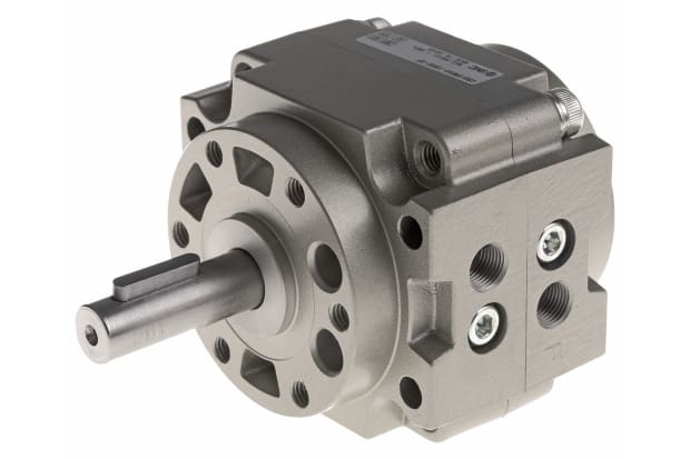
Electric rotary actuators are much more straightforward, as the angular motion they rely on is provided directly by the motor. But these are not just motors designed to go round and round – they are precision devices that need to be able to move just a few degrees if required. That means the motor is often connected to gearing to slow it down, produce more torque or speed up the rotation. It can also mean that the actuator will include sensors that send positional information back to the controller so they can fine-tune it.
Electric valve actuators are an example of rotary actuators. They rotate the disk 90 degrees to fully stop, fully open, or regulate flow through the pipework. Rotary actuators do often require a permanent voltage to keep them in place, however, losing power will return it to its default position, whether that’s fail-open or fail-closed.
Pneumatic vs Electric Actuators

As well as electric actuators, another family is pneumatic actuators, which use a compressed gas (usually air) to move a piston and force the shaft forward and backwards. The gas pressure can be applied to alternate sides of the piston to make it move in different directions, or the gas can enter and leave at just one side and rely on a spring to return it to its original position. Rotational motion can be achieved using a rack and pinion.
Pneumatic actuators still generally need electric power to compress the gas, but a single compressor can power multiple actuators, which can make them more efficient if used at scale. That does of course also mean that if the compressor fails, so do all the actuators, but backup compressors can solve that issue. Pneumatic actuators are also generally much faster and more powerful, but that energy release does come at the expense of precision. In general, electric actuators are preferred for smaller, more precise tasks, and pneumatic ones become more viable at a larger scale.


