- Published 16 Jun 2023
- Last Modified 29 Aug 2023
- 6 min
How Do NAND Gates Work?
Find out what NAND gates are, how their logic works, and when to use them in an electronic circuit.


NAND gates perform the opposite function of an AND gate. They do this by combining an AND and NOT gate together. This enables them to take any number of inputs and convert them into one output.
Known as a universal gate, NAND gates can work under the Boolean function without using any other date. In the case of NAND gates, this means the output always stays true (usually expressed as a 1) while at least one of its inputs remains false (typically expressed using a 0).
Using NAND gates enables the control and inversion of multiple inputs. This capability means NAND gates are typically used in security systems and temperature control or regulation circuits.
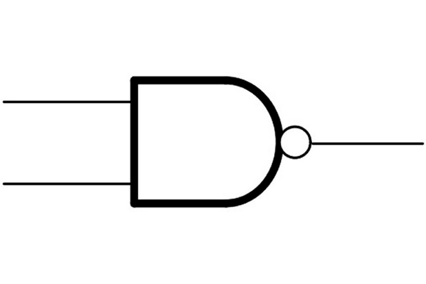
You can see the circuit symbol for a NAND gate on the right.
This article will explain exactly how these NAND gates work and outline ways you can use them effectively in your electronic circuits.
Truth Tables for NAND Gates
Truth tables are helpful for working out exactly how your NAND gate will perform in a circuit. Working under the Boolean function, they help you to figure out what the output will be as a result of multiple inputs.
In these tables, binary inputs and outputs are used. This means when the input is true (a signal is high or a switch is turned on) this is noted as a 1 and when the input is false (a signal is low or a switch is turned off) a 0 is used.
For NAND gates, the logic is that the output is 1 (or true) when all of the inputs are 0 (or false). In all other cases, the output is 0 (or false).
As such, the truth table logic for a NAND gate works like this:
Input A | Input B | Output |
|---|---|---|
0 | 0 | 1 |
1 | 0 | 1 |
0 | 1 | 1 |
1 | 1 | 0 |
As circuits get more complex and extra inputs are added, these truth tables can grow accordingly. For example, a four-input NAND gate truth table will be expressed like this:
Input A | Input B | Input C | Input D | Output |
|---|---|---|---|---|
0 | 0 | 0 | 0 | 1 |
0 | 0 | 0 | 1 | 1 |
0 | 0 | 1 | 0 | 1 |
0 | 0 | 1 | 1 | 1 |
0 | 1 | 0 | 0 | 1 |
0 | 1 | 0 | 1 | 1 |
0 | 1 | 1 | 0 | 1 |
0 | 1 | 1 | 1 | 1 |
1 | 0 | 0 | 0 | 1 |
1 | 0 | 0 | 1 | 1 |
1 | 0 | 1 | 0 | 1 |
1 | 0 | 1 | 1 | 1 |
1 | 1 | 0 | 0 | 1 |
1 | 1 | 0 | 1 | 1 |
1 | 1 | 1 | 0 | 1 |
1 | 1 | 1 | 1 | 0 |
When building a circuit using NAND gates, having a truth table with the correct number of inputs can help you work out exactly how the signal flow will work, ensuring you put the gates in the right place to reach the desired output.
Why Use Only NAND Gates?
Using only NAND gates won’t just help to control and invert multiple inputs but can be used for a variety of logical functions. Specifically, a NAND gate will make the output true when all the inputs are false and vice versa. This means the output won’t change when the signal drops or a switch is turned off in one of the inputs.
This effect is also known as a Sheffer stroke and can be used in a variety of ways, including:
- In home security systems: if sensors are attached to all windows and doors, they can send a signal 1 to the circuit when these are closed. This makes the alarm output 0. Then, if a sensor detects that a window or door is open, its signal will change to a 0. The alarm output will then become 1, setting off a sound or another function
- In freezer warning buzzers: in this case, the NAND gate is used as a NOT gate due to a single input. This means as the temperature gets warmer, the signal of the inputs drops towards 0. This causes the output to switch to 1, triggering an alarm or other warning system
- In light-activated burglar alarms: the two inputs in these systems are a switch and a light-dependent resistor (LDR). When the switch is closed or the LDR is in the light, these inputs will be 0, meaning the output will change to 1 and an alarm system will be triggered
NAND gates might also be chosen for a circuit due to their cost-effectiveness, durability, large storage capacity relative to their size, and the ease of replacing them if their flash memory is damaged.
How to Convert a Circuit to Only NAND Gates
The exact method of converting to NAND gates circuits will depend on the specific circuit’s function, complexity, and the types of gates currently being used.
However, there are a few rules which are helpful to keep in mind when making the conversion:

- The main function of NAND gates is to invert, meaning the output will always be opposite to the input
- Unlike NOT gates, NAND gates have two inputs and one output. This means you need to consider the effect of adding a NAND gate if there is only one input that needs to be inverted
- NAND is the opposite equivalent of an AND gate. This makes the switch between AND and NAND gates easy if you’re doing a straight conversion. However, you need to take extra consideration if you’re switching from OR to NOR gates
Carefully examining each part of the circuit in stages will mean you can consider exactly how switching to a NAND gate will affect the electronic flow. Doing this and keeping the rules above in mind will help you make a successful circuit conversion.
Why NAND and NOR are Called Universal Gates
NAND and NOR gates are called universal gates because they work under the Boolean function logic. Also known as logical gates, they follow binary functions and are part of a larger group of gates, including NOT, AND, OR, XOR and XNOR. As part of this group, both NAND and NOR gates can be used to recreate the function of the others in a circuit.
How to Make an OR Gate Out of NAND Gates
Similarly to a NAND gate, an OR gate converts two inputs into one output. An OR gate makes the output true (equivalent to 1) when either input is also true (equivalent to 1) and not when they are both true or false (equivalent to 0).
Therefore, to recreate an OR gate, three NAND gates need to be used (if the first two inputs can’t be combined). The main two inputs will be split and put into separate NAND gates. To recreate the OR function, these inputs then need to both be fed into a final NAND gate, reversing the initial inversion and producing an equivalent output.
Further Reading
Related links
- Logic Gates
- Guide to AND Gates
- Guide to Logic Gates
- Texas Instruments CD4023BE 14-Pin PDIP
- Texas Instruments SN74LS00N 14-Pin PDIP
- Texas Instruments SN74LVC1G00DCKR 2-Input NAND Logic Gate, 5-Pin SC-70
- Texas Instruments CD4023BM, Triple 3-Input NAND Logic Gate
- DiodesZetex 74AHC1G00QSE-7 2-Input NAND Schmitt Trigger Logic...

