- Published 17 Jan 2023
- Last Modified 5 Aug 2024
- 16 min
A Complete Guide to Resistors
What do resistors do and what are the different types of resistors? Learn more in our comprehensive guide.

For many engineers, choosing the right resistor for their application is simply a matter of calculating the correct value and tolerance, then looking for the most cost-effective solution. Why then, are there so many different types of resistors? This guide aims to offer some insight into the world of resistors and their key parameters.
We will start with the basics, covering what resistors do and the resistor colour code, before taking a quick overview of the major types, highlighting their key characteristics, then finally looking at the more detailed specification areas that an engineer will come across during the product design process.
What is a Resistor and What is its Circuit Symbol?
A resistor is an electrical component that restricts the flow of electrical current in a circuit. The analogy often used to explain its operation is to consider current as water flowing in a hosepipe; a resistor can be considered as a constriction in the pipe that limits the flow of water.
Most people will be familiar with Ohm’s law: V=IR. V is the voltage across a resistor, I is the current flowing in the resistor, and R is the resistance. This is the equation that connects current, voltage and resistance and is the basis of working with resistors (and other passive components).
At a microscopic level, resistors are made from a variety of materials that are conductors, but not perfect ones, so the ability for electrons to flow is impeded by the atomic structure of the materials chosen. By varying the conductor’s characteristics such as the material’s conductivity, the surface area and the lengths of the material used, it is possible to control the resistance to the desired accuracy. Resistance is measured in Ohms, and the symbol for the unit is Ω.
What Do Resistors Do in a Circuit?
Resistors have many uses in circuits. Below are some of the more common functions; most applications require multiple resistors in serial or parallel configurations. Some of the more common uses of resistors include:
- Potential dividers. Two or more resistors in series will give a voltage at their junction point proportional to the ratio of their values. This functionality is widely used in circuits for generating intermediate voltages
- Biasing resistors. Transistors and many other devices need to have their AC and DC operating characteristics and gain values set up for correct operation. This is done with multiple resistors and is often called biasing
- Op-amp gain and feedback. Most op-amp circuits need to have their gain and feedback functionality set by resistors external to the amplifier chip; resistors are the primary means of doing this
- Current limiting. Resistors can be used to limit the amount of current that flows in a circuit element. This is a useful safety function in many circuits e.g. limiting the current that can flow into an LED to manage its brightness
- Impedance matching. To maximise power transmission at high frequencies the impedance of the receive and transmit ends of a circuit need to be the same. Resistors can perform at least part of this requirement
- Current measuring. Many circuits need to know how much current is flowing, however, it is much easier to measure voltage, so inserting a resistor into the circuit to ‘develop’ a voltage – remember Ohm's law- is a common technique for measuring current
- Data and address bus pullups. This functionality helps to reduce noise issues on high-speed computer busses. When a data bus tri-states or is driven high, it is often necessary to pull it into a known state or to make sure its output high is well above the switching point of other logic elements on the bus, and a pull up helps to do this
Types of Resistors
There are many different types of resistors and they can be made from various materials, all of which have their own unique advantages and disadvantages. Before looking at the materials, it’s worth considering the various available configurations.
Fixed Value Resistors
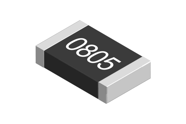
These are the predominant type of resistor configuration, and as the name suggests, they have a fixed resistance value. It is possible to buy a resistor of any ohmic value that you require, however in the vast majority of cases, it is possible to ‘tweak’ the circuit to change the value that is required. For this reason, all manufacturers will supply families of resistors, with a given number of resistors to each decade of value.
So, for instance, a common family is the E24 family. This has 24 values between 100Ω and 1000Ω or between 10KΩ and 100KΩ. The values in the range are chosen so that when you take the tolerances for each value into account, you have coverage over most possible values. The number of values in a family depends on the accuracy and tolerance required, so the E192 family has far more values to choose from, with tolerances down to 0.1%. This, of course, can increase the cost of the resistors.
Variable Resistors
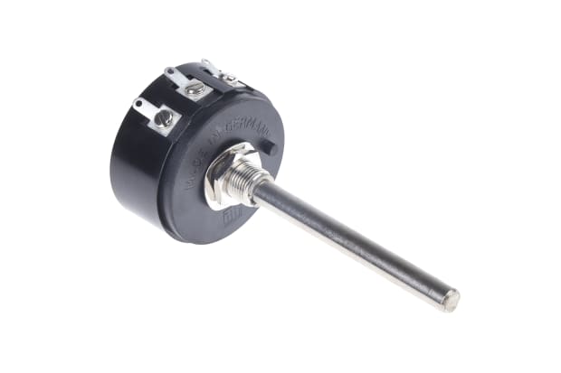
Variable resistors (also known as potentiometers) are resistors that can have their value changed either by turning a shaft or in pre-set pots by a screwdriver.
A variable resistor is a three-terminal device. The centre pin with the arrow is known as the wiper and is where the variable resistance is available. The devices come in the form of a moveable contact running along a resistive track, or in the case of multiturn devices used as panel controls, a tightly wound wire. Although useful for tuning resistance values in a circuit, ‘pots’ can be prone to movement of the wiper because of vibration and hence can be problematic if wrongly specified.
Resistor Networks
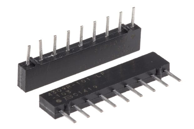
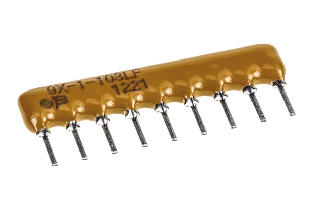
It is often the case that multiple resistors of the same value are needed, in data bus pull up applications, for example. For these applications, it is possible to purchase resistor packs either as single inline (SIL) or dual inline (DIL) packages. They can come as multiple non-connected resistors, or with one pin of each resistor connected to a single contact on the package. Although this solution can be more expensive on a per resistor basis, the mounting costs are of course lower as only one insertion is required and so a balance is possible. This consideration has led to the availability of dual resistors in a single pack for potential divider applications.
Resistor Value Marking
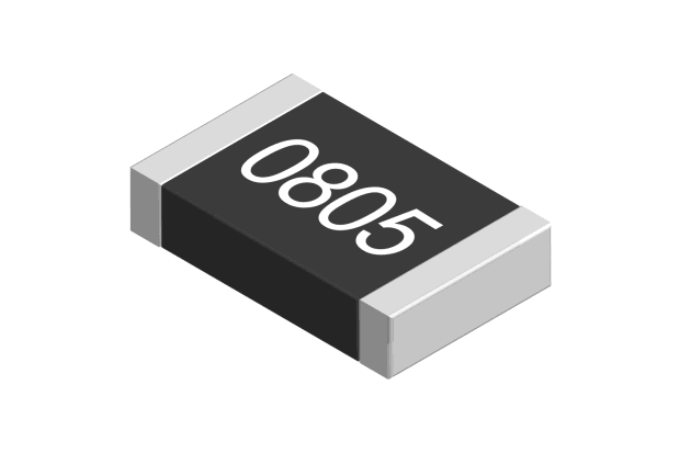
Most resistors have value marked on them. For surface mount resistors, this can be one of several options. They can be a 3 or 4-digit code representing the value using a value and multiplier system. For example, 102 would represent 10²or 1kΩ, the 4-digit type could be 1002 which is 100 x 10² or 10KΩ. For low values, you may see something like 4R7 which is 4.7Ω. R is used as a decimal point in this instance.
Given the minute size of surface resistors, these can be extremely difficult to see, especially now that SMD resistors are available in tighter tolerances, and with more values. For this reason, the EIA96 system is used. This involves a lookup table where a three-digit value is used to point to a value and multiplier, hence specifying the value in a minimum number of digits.
Resistor Colour Code
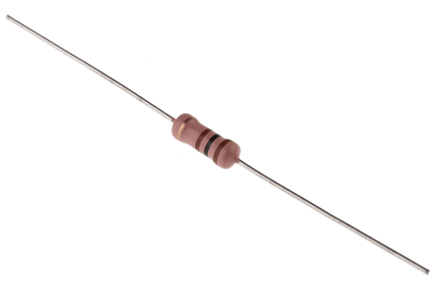
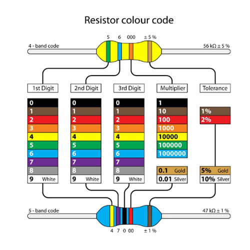
The system is a little simpler for through-hole resistors. A colour code has been in place for many years and is still current. This diagram shows the system in use. Each resistor has three or four bands specifying the value, plus a tolerance band. For a 4-band resistor, the first two bands are numerical values and the third band is a multiplier.
If, for instance, we had a case where the first two bands were red, and the third band was orange, then the resistor value would be 22KΩ. If the fourth band was also red, then the resistor would have a tolerance of 2%. If we take the case of a 5-band resistor with the first three colours as red, and the fourth as brown, we would have a value of 2.22KΩ.
Resistive Materials
Having looked at the basics of resistor design and the configurations that are possible, it is now time to look at the materials that are used in resistors and to highlight their advantages and disadvantages.
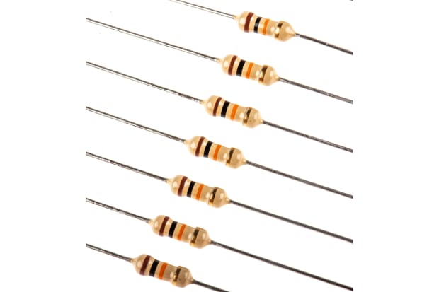
Carbon Film Resistors
Carbon film resistors have largely been replaced by metal types for general purpose applications, due to their poorer tolerance and noise characteristics. However, they are still used in some specialist applications.
The resistor is constructed by forming a carbon film onto a ceramic substrate. This has multiple advantages. Firstly, the film is largely non-inductive, secondly, the ceramic is an excellent insulator for heat and electricity, and thirdly, the layout has a large cross-section. So, their low inductance makes them useful for high-frequency applications and their larger cross-section lends itself to higher operating voltages and better survivability to transients than many other types. As a result, although less widely used, they are still commonly available.
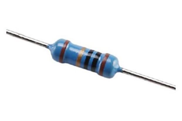
Metal Film Resistors
Metal film resistors are made by placing a layer of metals such as ruthenium onto an insulating substrate. They are available in a large number of types and packages and compared to carbon film resistors, their construction is simpler to mass-produce and smaller physically.
Metal film resistors have largely replaced carbon film resistors in most standard applications due to their lower noise, tighter tolerances and generally better temperature coefficients. Although often perceived as a ‘standard’ resistor, they have evolved from a lower performance base to the point where they are offered with quite high precision (0.1%) and low TCRs in the single-digit PPM/C range. It’s worth noting that metal film resistors are offered in both trough hole and surface mount (chip resistor) types.
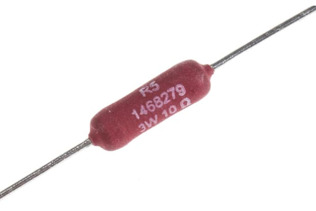
Wirewound Resistors
Wirewound resistors have some characteristics that are attractive in specialist applications, such as high precision instrumentation where tolerances much better than 0.01% and very low-temperature coefficients (TCR) are required.
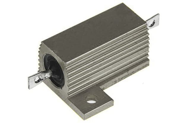
They are also often the resistor type of choice for high power applications (examples rated up to 100s of watts are available). However, it’s worth noting that as they consist of wire wound around an insulated core, which is an inductor by definition, these resistors are not recommended for high-frequency applications, and are generally not available in surface mount form.
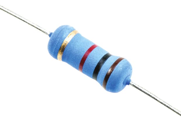
Metal Oxide Resistors
These items are similar to metal film resistors, save that the resistive element is an oxide (often tin). Their performance is subtly different from metal film in that they typically are better for higher voltage and higher power applications than metal film parts.
However, they are typically offered in smaller ranges and may offer reduced tolerances and TCRs. Again, they are offered in both surface mount and through-hole types.
Metal Strip Resistors
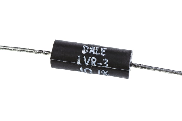
These are specialist resistors generally used for current measuring applications in power supplies. They are characterised by often very low ohmic values, so they are offered with relatively low-temperature coefficients and medium power dissipation to minimally affect the overall circuit operation.
As the name suggests, they are effectively a laser-trimmed strip of metal. Another key characteristic for these devices is a low thermal resistance as they are potentially carrying high currents which may lead to the need to dissipate heat generated in operation.
Resistor Specifications
What are the key characteristics and specifications that affect the choice of resistor? Factors that should be taken into consideration include initial tolerance and value selection. However, the tolerance or variation of the value of a resistor is affected by multiple parameters, as explained below.
Temperature Coefficient
This is a measure of the variation of the nominal value as a result of temperature changes. Generally quoted as a single value in parts per million per degree centigrade (or Kelvin), it can be positive or negative. The equation for calculating the resistance at a given temperature is:
Rt=Ro[1+α(T-To)]
Where Ro is nominal value for room temperature resistance, To is the temperature at which the nominal resistance is given, T is operating temperature and α is the TCR.
Put simply, a 1 MΩ resistor with a TCR of 50ppm/K will change by 50Ω per 1 degree of temperature rise or fall. This may not sound like much but consider if you were using this resistor as the gain resistor in a x10 non-inverting amplifier circuit with 0.3v on the + input. The worst-case change in output could be as much as 7.5mv which is equivalent to about 5LSBs in a 5v 12-bit ADC circuit. This kind of change can be quite noticeable in precision design. Remember also that the TCR is quoted as ±x ppm/C so it is feasible, although unlikely, that the second resistor in the circuit could change in the opposite direction hence double the possible error. Finally, it’s worth noting that some precision resistors quote variable TCRs over the temperature range the circuit is operating in, and this can complicate the design process significantly.
Resistor Ageing or Stability
Ageing and stability are a complex amalgam of multiple changes to the value of a resistance value over time and are the result of temperature cycling, high-temperature operation, humidity ingress and so on. Typically, the value will lead to an increase in resistance over time as conduction atoms migrate within the device.
Thermal Resistance
The thermal resistance is a measure of how well the resistor can dissipate power into the environment. In practice, engineers use thermal resistance to model the heat dissipation for a system – it is thought of as a set of series ‘thermal resistors’, each representing one element of the heat dissipation of the system.
This is mainly important if the design means the resistor is running at or near its maximum value and can significantly affect the long-term reliability of the system. An example of where this parameter could be used is to calculate the size of a PCB pad or ground plane requirement that would be used to keep the resistor’s value and operating temperature within acceptable limits.
Thermal and Power Rating
All resistors come with a maximum power rating, specified in watts. This can be anything from 1/8th watt right up to 10s of watts for power resistors. In a first pass analysis, the engineer would check that the resistor is operating within its rated value. The equation for calculating this is P=I² R, where p is the power dissipated in the resistor, i is the current flowing and R is the resistance. Sadly, things can be more complicated than this; for exact work, the engineer needs to take account of the thermal derating curve for the resistor. This specifies the amount by which the designer needs to de-rate the maximum power dissipation above a given temperature.
This might seem theoretical as often the de-rating kicks in at quite high temperatures, but a power circuit in an enclosed housing in a hot region can often exceed the cut in point and the maximum power dissipation will need to be reduced appropriately. It’s also worth noting that the maximum operating voltage of a resistor is de-rated with power dissipation.
Resistor Noise
Any electronic component that has flowing electrons is going to be a source of noise, and resistors are no different in this respect. In high gain amplifier systems or when dealing with very low voltage signals, it needs to be considered.
The major contributor to noise in a resistor is thermal noise caused by the random fluctuation of electrons in the resistive material. It is generally modelled as white noise (i.e. a constant RMS voltage over the frequency range) and is given by the equation E=√4RkT∆F where E is the RMS noise voltage, R is the resistance value, k is Boltzmann’s constant, T is the temperature and Δf is the bandwidth of the system.
It is possible to lessen system noise by reducing the resistance, the operating temperature or the system’s bandwidth. Additionally, there is another type of resistor noise called current noise which is a result of the electron flow in devices. It is rarely specified but can be compared if the standard numbers using IEC60195 are available from the manufacturer.
High-Frequency Behaviour
The final challenge to consider is the high-frequency performance of the particular resistor. In simple terms, you can model a resistor as a series inductor, feeding the resistor which has a parasitic capacitor in parallel with it.
At frequencies as low as 100Mhz (even for surface mount resistors which have lower parasitic values than through-hole parts) the parallel capacitance can start to dominate, and the impedance will drop below nominal. At a higher frequency still, the inductance may predominate, and the impedance will start to increase from its minima and may well end up above the nominal value.
Conclusions
Although we have covered many of the significant parameters that may be encountered when designing a circuit with resistors in it, there are still more which should not be overlooked.
In many cases, a standard 1%, metal film, 0.125w resistor will be absolutely fine for the application. However, there are many products where a more detailed appreciation of the resistor specification will be necessary. These include power supply designs, audio work, high-frequency designs and products that must deal with high ambient temperatures. In these cases, a detailed inspection of the specifications and special care when selecting the product will lead to a more reliable design and potentially avoid a time-consuming redesign.
Key Products
Through Hole Fixed
Browse our extensive range of through hole fixed resistors and discover the ideal resistor for your requirements.
Surface Mount Fixed
With a range of different sizes and tolerances available, browse our full selection of surface mount fixed resistors online.
Panel Mount Fixed
Explore panel mount fixed resistors and shop products from leading brands including Arcol, TE Connectivity, Vishay, and more.
Resistor Arrays
Click through to view our full range of resistor arrays and shop online with RS.
