- Published 30 Jan 2023
- Last Modified 25 Mar 2024
- 9 min
A Complete Guide to Thyristors
Read our thyristors guide, explaining what they do, their applications, how they work, and the different types.

Updated April 2022
What is a Thyristor?
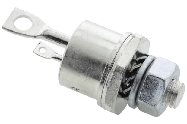
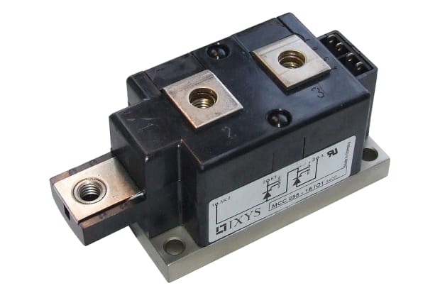
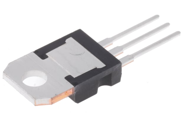
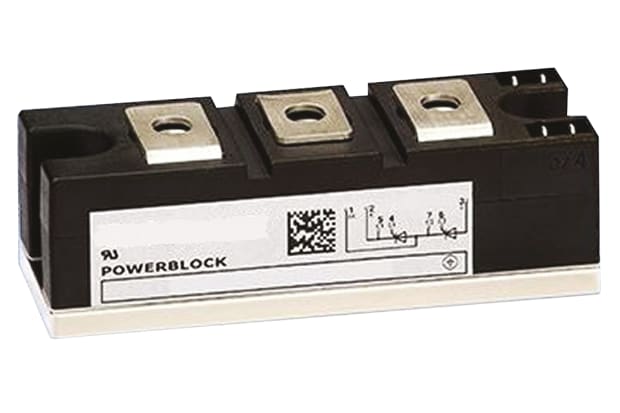
What is a thyristor? They are powerful on-off switches for a range of both alternating current (AC) and direct current (DC) equipment, primarily within industry. Rectifiers are electronic components that convert alternating current into direct current when charge flows through them.
These powerful devices are solid-state switches, meaning that they are made from semiconducting components such as transistors and diodes. Semiconductor devices have electrical conduction that is halfway between a full conductor, like copper, and an insulator like glass.
The name thyristor is derived from a combination of transistor and thyratron (an earlier gas-filled tube with a similar function). Originally developed in the 1950s, these devices are also often referred to as silicon-controlled rectifiers (SCR) because they are made from four layers of silicon, which is a widely used semiconducting material.
Originally, SCR was a brand name used by General Electric for one type of thyristor. The two terms are now usually used synonymously.
What Does a Thyristor Do?
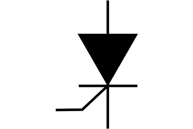
Thyristors are bistable switches, meaning that they have only two possible states - on or off (0 or 1). These remain stable even when the device is powered down. Current models will activate - i.e. move from the state of being off to on - as soon as current reaches the control gate (entry point). They will continue to allow current to flow through them until it drops to zero or when the current ends or changes direction.
The latter is known as reverse biasing or reverse voltage. Earlier models relied on a reversal in the current to move from the on state to the off state, but it is possible to deactivate newer models via the control gate. These are sometimes called gate turn-off (GTO) thyristors.
Controlled rectifiers are high gain devices, meaning that the current present at the control gate can control a much higher level of current between the anode and cathode. As a result, they are classed as current operated equipment.
Thyristor Applications
Despite being physically small devices, thyristors can control high voltages and levels of current and so are used in high voltage, direct current power transmission lines.
Other uses include:
- Power switches in factories and similar industrial settings
- Vehicle ignition switches
- Controlling the speed of electric motors
- Liquid level regulators
- Pressure control systems
- Surge protectors
These devices are also widely used in a range of electrical circuitry. Applications include:
- Inverter circuits
- Oscillator circuits
- Chopper circuits
- Power switching circuits
- Relay replacement circuits
- Level-detector circuits
- Logic circuits
- Phase-control circuits
- Speed control circuits
- Timer circuits
How Does a Thyristor Work?
Now for the key question - how do thyristors work? They typically have three leads or electrodes (points at which electricity enters or exits). These are called the anode, the cathode and the gate (or control gate). The first is the positive terminal and the second the negative one, while the gate controls the main anode-to-cathode current, triggering this via an external pulse. Some models feature two or four electrodes.
Within a typical SCR, there are two alternating layers of N-type (negative) semiconductor and P-type (positive) semiconductor. This makes four layers altogether, with three junctions between these. The four-layered silicon in each is electrically treated to increase the number of either negative or positive charge-carrying electrons. They are also known as NPN and PNP semiconductors, referring to the pattern of positive and negative electrons in each.
If no current is flowing into the device via the gate, it will rest in an off state, with the central junction (of three) reversed, opposite to the anode and cathode, so current cannot pass through whatever the direction of the device. This is referred to as forward blocking mode or negative blocking mode, depending on the direction.
For current to flow as required, the anode must be positive, and the cathode must be negative. Once the gate current launches, positive and negative charge flows into the four layers of silicon, activating each in turn as it moves from one layer of the semiconductor to the next through the device. Once all four layers have been activated, the current can flow freely through the device. The thyristor is now forward conducting; it has latched on (moved into an on state) and it will remain latched until the current is switched off outside the device - usually the current to the entire circuit. The gate current is not required to maintain the current between the anode and the cathode.
SCR Circuit with AC
Thyristors have slightly differing circuitry, depending on whether they are intended for use with an AC or DC current.
The diagram illustrates an SCR circuit for use with AC.

This diagram shows the typical layout of a circuit for use with DC.

Thyristor vs Transistor
A transistor is a standard electrical component used to switch electrical signals on or off and to amplify them. Their invention in the early 20th-century enabled the development of radio and long-distance telephony. Despite their versatility, however, they do not work well with high voltage currents and are best suited to low power milliamp currents. To put that into perspective, a milliamp is one-thousandth of an amp. By contrast, thyristors can operate with much higher levels of power, 5-10 amps and hundreds, even thousands, of volts.
They also rely on a steady power input to operate correctly. In a transistor, a low level of current is amplified on entry, but in some devices, this is not adequate. An intruder alarm requires a different kind of reaction. You need a low level of current in the alarm trigger (e.g. a motion detector) to launch a higher current within the alarm to set off the bell or alert - and this higher current to continue even when the trigger current stops. A transistor cannot do this, but a thyristor can. The motion detector or similar device triggers the gate current and this, in turn, triggers the flow of current between the anode and the cathode. The latter will continue - remain latched on - even when the gate current ceases.
Thyristor vs Diode
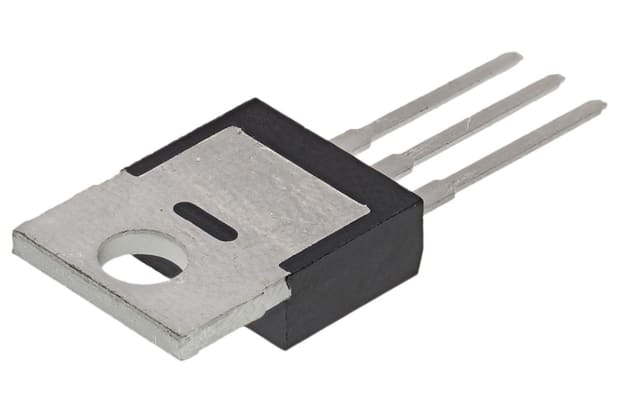
Diodes are relatively simple, inexpensive components with only two terminals (one positive and one negative), an anode (also known as a plate), and a cathode. Electricity flows through in one direction only. In electrical terminology, they are forward biased rather than reverse biased.
Diodes are mainly used for switching or converting current. They have only two semiconductor layers - one positive and one negative - with a single electrical junction between these.
By contrast, most thyristors have three terminals and four layers, with three junctions separating these. They are designed for high power applications. Diodes are designed for low voltages but do not require a gate pulse to activate them, unlike thyristors.
Types of Thyristor
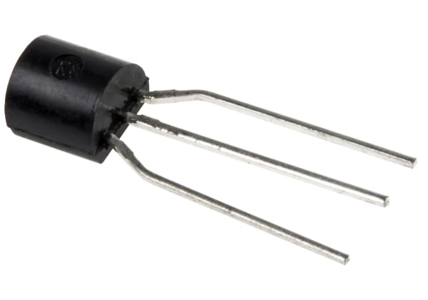
Most thyristors are three lead devices, meaning that they have three electrodes - an anode, a cathode, and a control gate to trigger the flow of current between the other two.
However, less common two lead models have only two electrodes, and current flows are triggered when the difference in charge between each hits or exceeds a defined breakover voltage, switching them from off to on.
You may also find:
- Silicon controlled switches (SCSs): these have an additional anode gate, which is used to deactivate the device when a positive voltage is applied
- Diacs: these thyristor-diode hybrids have four layers and will accept current flowing in either direction. Despite the name, derived from diode AC switch, diacs will work with both AC and DC
- Triacs: these devices are bidirectional, meaning that they will conduct electricity in either direction. They will switch both AC and DC
- SIDACtors: these models work without a control gate, relying on short-duration electrical surges instead
- IGBT: insulated gate bipolar transistors have four layers and three terminals but are designed to function purely as a transistor and not a thyristor
- PCTs: phase control thyristors are used to limit AC currents by moving equipment in and out of a conducting state at predetermined intervals
Advantages of Thyristors
Thyristors have become standard components because they offer several advantages. These include:
- Speed and the ability to switch currents in microseconds
- Ability to control high voltages and high levels of power
- Lack of moving parts and high reliability
- Ability to control direct current devices, not just routine alternating current
- Quick and easy activation
- Inexpensive
- Ease of operation
- Relative simplicity
- Small size
How to Check a Thyristor
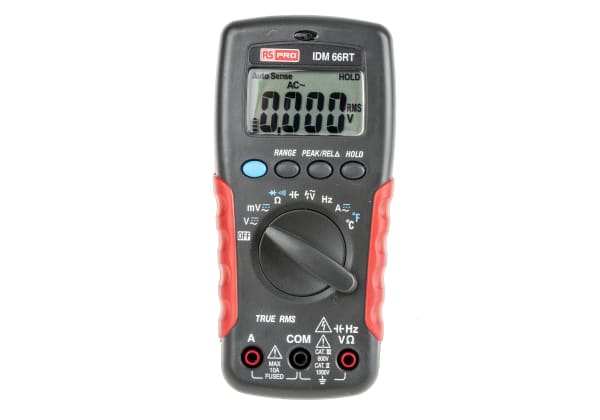
As with any electrical device, it is necessary to check thyristors from time to time to ensure they are working correctly. The easiest way to do so is to use a multimeter.
How to Test a Thyristor
Multimeters are industry-standard electrical testing devices, able to measure voltage, current, and the strength of electrical resistors.
Here is how to test a silicon-controlled rectifier using a multimeter:
- Connect the anode (entry terminal) on the thyristor to the positive (red) lead on the multimeter. Connect the cathode (exit terminal) to the negative (black) lead. Switch the meter to diode test mode - the diode (two-terminal component) in this case being the thyristor itself. Assess
- Set the multimeter to high resistance mode. It should show an open circuit. Then reverse the position of the leads and the device should still show an open circuit
- Return the leads to their original positions, this time adding the gate terminal to the positive lead. The multimeter should show a low level of electrical resistance. This indicates that the SCR is in the on position, and this should continue once the gate terminal is disconnected
- If the multimeter passes the above checks, it is working correctly
Thyristor Manufacturing Companies
Vishay
With a wide range of thyristors and related products available, shop Vishay devices with RS.
STMicroelectronics
Leading brand STMicroelectronics has a wide variety of top-quality thyristors available. Click to browse the full range.
Infineon
Explore Infineon thyristors and buy online with RS for top-quality components ideal for your application.
